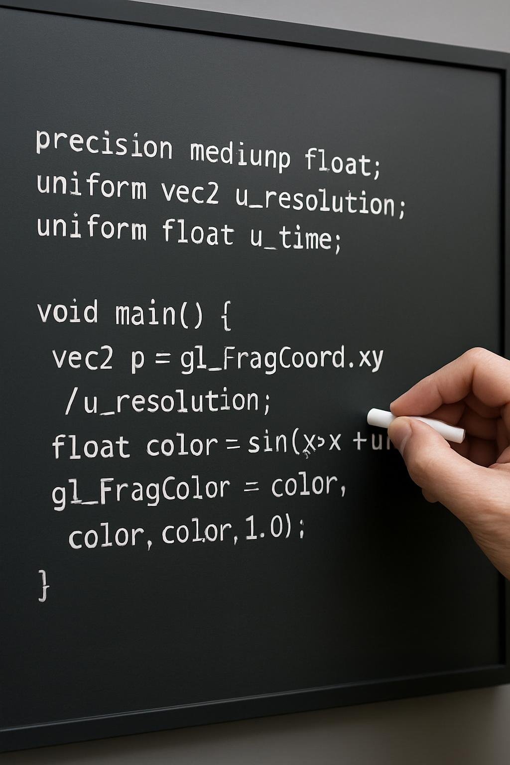
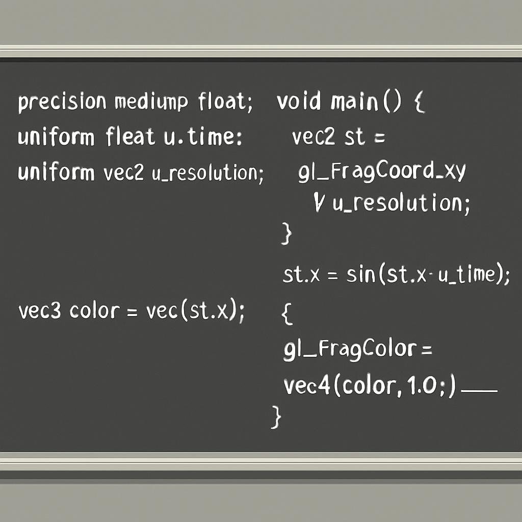
If you work on any computer languages before, you will find yourself in a completely new dimension while programming in shader. You don’t have much tool to debug these codes nor even a log, as these codes are run on the GPU of the graphics card (hardware). So to master shader you need to learn how to debug or validate your logic. Will go through these tricks as we progress further.
How do we know the origin of the shader coordinate?
To master the shape generation you need to understand the UV’s, one of the techniques to know about your UV’s is to identify from where it starts (origin of the UV’s ) and end of the UV’s.
In shader you only have colours to understand anything. If we shade the pixel base on the UV’s and observe the colours you will know about the origin.
If we calculate the finalColor of each pixel base on the below command. We will get the gradient as shown in the image below, which goes from black to red and in-between these we have an interpolated value of black to red.
finalColor=vec4(uv.x,0.0,0.0,1.0);
In GLSL (0, 0) is on the bottom left corner. In some shader environments it might be on the top left corner, using gradient shader you will know where our (0, 0) lies in the geometry plane.
In most of the cases this technique is used to troubleshoot the shader.
Note: Play around by uncommenting lines in code. and build your logic, how code changes the pattern.
Uncomment line “finalColor=vec4(vUv.x,vUv.y,0.0,1.0);” in the code.
Area with black color represents that xy=(0.0, 0.0) is at the bottom, see bottom left corner on the image.
How To Shift Origin to Center in Shader ? In some cases we required the origin to be on the centre of the geometry plane. As we now know that our coordinate starts from bottom-left corner (0.0, 0.0) to top-left corner (1.0, 1.0).
uv = uv * 2 If you multiply 2 with uv you will get the uv=(0.0 to 2.0)
uv = uv * 2 – 1
Now if you subtract 1 you will get the uv=(-1.0 to 1.0)
To master the shape generation in shader you need to understand how shader programs run for each pixel and shade them. This tutorial gives you the basic understanding of how you can visualize and draw any shape. Imagine a texture(Image) with a bunch of blank pixels as shown in the below image, and you have to shade each pixel one by one in order to generate the shape. Where uv denote the axes of 2D texture, as x, y and z are already used to denote the axes of the 3d object in model space. These uv are in Normalised Device Coordinate (NDC) space i.e (0.0 to 1.0).
Observed above image carefully how your screen coordinate are plot, these coordinate are on NDC (Normalize Device Coordinate). Assume you have the above screen with uv, Let’s take some examples to understand how we can shade these pixels.
Ex1. Can we shade half of the screen with red and the other half with green?
OpenGL (Open Graphics framework) is a sophisticated and versatile cross-platform graphics framework that is used to render 2D and 3D computer graphics. It is a vital tool in the area of computer graphics and has had a significant impact in a variety of fields such as video games, virtual reality, simulations, and scientific visualisation. This article will explain what OpenGL is, its history, latest update, and its importance in the field of 3D graphics.
The Origins of OpenGL
Silicon Graphics Inc. (SGI) developed OpenGL as a 3D graphics API (Application Programming Interface) in the early 1990s to offer a standardised method of interacting with graphics hardware. It was intended to be a fix for the issue of disparate operating systems and graphics hardware. Because of SGI’s choice to make the specification open, numerous platforms have adopted it, making it an open standard.
Key characteristics and abilities:
1. Cross-platform: The cross-platform interoperability of OpenGL is one of its main benefits. Windows, macOS, Linux, and even mobile platforms like Android and iOS are just a few of the operating systems on which it can be utilised.
2. Efficiency: OpenGL is well-known for its efficiency in harnessing the power of the GPU (Graphics Processing Unit) to expedite rendering, making it a good choice for real-time 3D applications.
3. Flexibility: OpenGL has a large range of functions and capabilities, making it a versatile tool for various 2D and 3D graphics applications.
4. Open Standard: Because OpenGL is an open standard, it is not bound to any one hardware vendor, offering developers greater flexibility in their hardware selection.
Applications:
OpenGL is the foundation of many applications and industries, including:
1. Video Games: The game industry mainly relies on OpenGL for real-time rendering of 3D graphics. Many prominent games, both old and new, employ OpenGL graphics engines.
2. CAD (Computer-Aided Design): OpenGL is used by engineers and architects to create detailed and dynamic 3D models.
3. Visualization of Scientific and Medical Data: OpenGL is used to create intricate data visualizations that enable academics to get insights from enormous datasets.
4. Virtual Reality (VR) and Augmented Reality (AR): To create immersive and interactive worlds, VR and AR apps rely on OpenGL.
OpenGL’s latest updates:
OpenGL 4.x and Beyond: OpenGL has reached version 4.x; new features and functionalities were added with each release. The rendering quality, performance, and support for contemporary graphics technology were all improved by these improvements. These versions added features including compute shaders, improved texture compression, and tessellation shaders.
Impact of Vulkan: Vulkan, a low-level graphics API created by the Khronos Group (the same company that controls OpenGL), gained popularity although OpenGL remained a well-liked option. Modern gaming and 3D applications are better suited to Vulkan’s higher performance and lower-level hardware access. This caused some developers, particularly in the gaming sector, to progressively switch to Vulkan for new projects.
OpenGL ES: For mobile and embedded devices, OpenGL ES (OpenGL for Embedded Systems) has remained essential. It changed to meet the needs of augmented reality, virtual reality, and mobile gaming applications.
WebGL: Based on OpenGL ES, WebGL has gained popularity for rendering 3D visuals in web browsers. It provided a link between web technologies and OpenGL-based rendering, allowing developers to generate dynamic 3D content directly within web applications.
Cross-Platform Development: One of the main advantages of OpenGL continues to be its cross-platform interoperability. It remained a popular option for programmes that needed to function on different platforms, including Windows, macOS, Linux, and mobile devices.
Contributions from the Community: The OpenGL community, which is made up of programmers, fans, and researchers, has continued to advance the technology. Extensions and tools that improved its functionality were produced by this collaborative effort.
Longevity of OpenGL: While more recent APIs like Vulkan provided up-to-date options, OpenGL continued to be useful for a variety of applications, including those involving older systems and educational settings. It was a useful tool because of its vast documentation and wide support across numerous platforms.
Future challenges include:
Like any other technology, OpenGL has had its share of difficulties. To stay relevant in the face of more recent and effective APIs like Vulkan and DirectX 12, OpenGL has had to change. Even though OpenGL is still a strong option for many applications, particularly in cross-platform and legacy situations, it is rapidly making way for newer standards in the gaming and high-performance computing sectors. In summary, OpenGL has been essential to the development of computer graphics. It has become a fundamental tool for developers and designers due to its openness, cross-platform compatibility, and versatility. Although its dominance may have changed in some areas, its legacy in the field of 3D graphics is obvious, and its effects can still be seen today in a variety of fields.
Following are the step needed to render any Mesh on to the screen:
Set vertex and fragment shader program(instruction) on to the render pipeline.
Load mesh data onto the RAM.
Pass Mesh data from CPU to GPU/Render pipeline for rendering.
Now all the mesh will be rendered by the same shader program passed on step 1, until we set a new shader program.
Working of shader: Even though we are running this code for the web the same code will also run for other platforms that use OpenGL.
Vertex Shader:
Its main function is to convert the vertices’ 3D coordinates from the local space of the model to the 2D screen space where they will be shown.
The vertex shader’s primary function is to transform vertex locations. This entails using transformations such as translation, rotation, and scaling to position the 3D object within the 3D scene.
As in c/c++ we have a starting point main() function, same as in the shader we have a starting point main() function for vertex shader.
void main() { }
position : This is the mesh vertex xyz coordinate position in object space.
modelViewMatrix: Move 3D position from model(object) space to world(scene) space.
projectionMatrix: Convert 3D coordinates to 2D screen coordinates (screen space). This transformation takes into consideration perspective, making items farther away from the camera appear smaller.
gl_Position: is a predefined vec4 variable defined by OpenGL which is available only in the vertex shader. and used to hold processed vertex position.
Fragment Shader: Following program will render each pixel of the object to red.
gl_FragColor: It’s a built-in global variable in glsl that will be used to determine the colour of each pixel.
Try changing colour to green or blue. gl_FragColor = vec4(0.0, 1.0, 0.0, 1.0); // rgba
Attribute : is used to describe the position, normal, or texture coordinates of each vertex in a mesh. It is set once per mesh and does not change throughout the rendering process.
Uniform : is used to specify global data that is constant for all vertices or fragments in a rendering call. Examples of uniform variables include the view matrix, projection matrix, and texture samplers. Uniforms are set once per rendering call.
Varying : is used to pass data from the vertex shader to the fragment shader. The varying data is interpolated across the surface of the triangle to which each fragment belongs. The interpolated value is then used in the fragment shader to compute the final color of the pixel.
Each type of variable has a specific purpose in the rendering pipeline.
attribute: attribute is a read-only variable that stores information about each individual vertex, such as vertex position, colour, normal, and uv coordinate etc. attribute cannot be used within the fragment shader.
uniform: As GPU manages large numbers of parallel threads, to colour pixels of the image. Also each parallel thread doesn’t know about what other threads are doing. To keep them performing properly we need to send some inputs from the CPU to all threads. And that input has to be read only, in other words, each thread receives the same data which it can read but cannot change. Those inputs are called uniforms.
Here, I am adding u_ prefix to indicate that these are the uniform variables.
Lets Understand This With Following Example: Shader is a computer language, which is designed to program and perform mathematical calculations.
Consider the following scenario:
Suppose we have a green colour light in the world, at some position and pointing to some direction.
There is a cube object in the world.
And your eye or camera watches this object from some point.
Now to render the cube based on the light, shader needs information like light direction, colour and position to perform calculation in the shader. A uniform variable is a parameter that the cpu or in other word our application (cpp/javascript) passes to the shaders. As the name implies, the value stored in a uniform variable will be the same for the shader programme and cannot be changed by shaders (read-only) across all GPU threads. Uniforms can be accessed by both the vertex and the fragment shaders. uniforms are used to store data like, light direction, camera position in world, fog value, shadow maps etc.
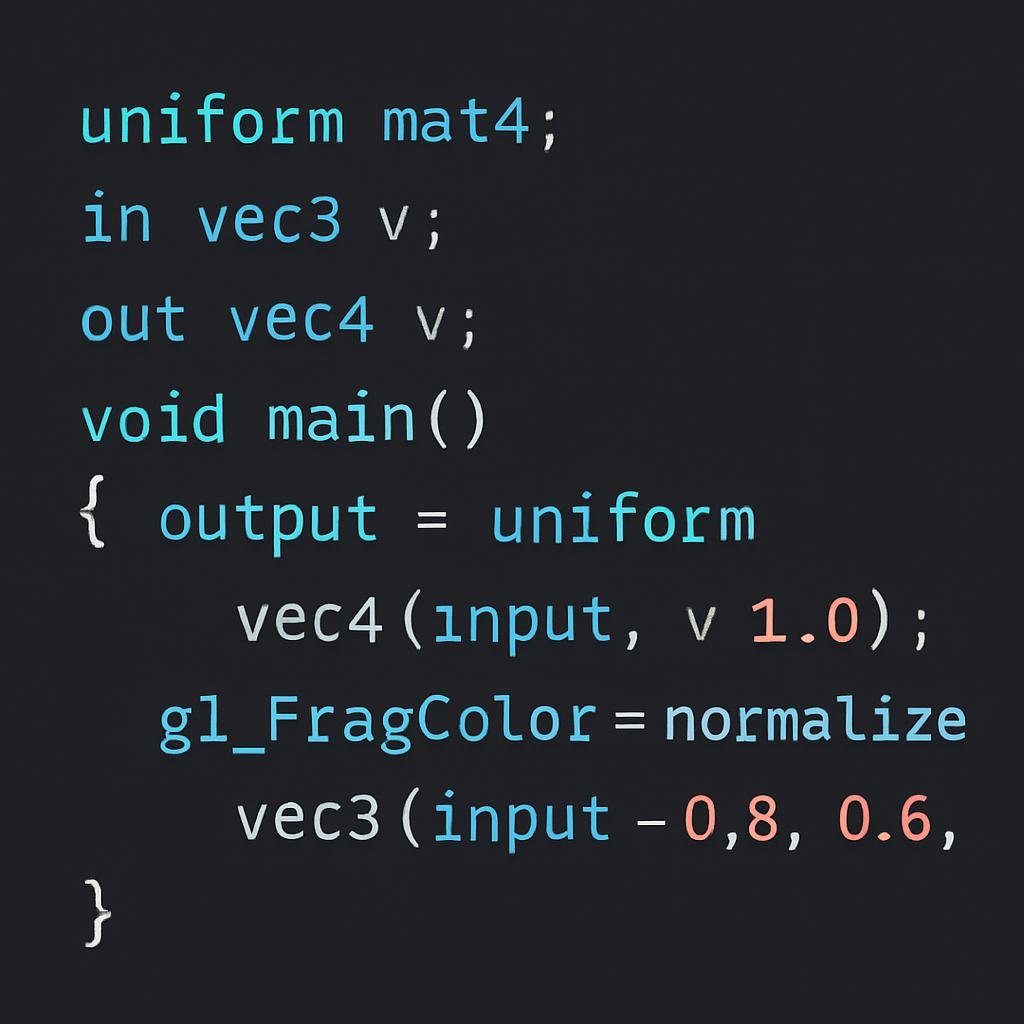
varying: are parameters that the fragment shader receives from the vertex shader. The value of each variable for each fragment will be interpolated smoothly during rasterization from the values of neighbouring vertices.varying is deprecated in the new version of OpenGL and varying is replaced with the in and out qualifiers which give clarity which variable is input to vertex shader and which is output for fragment shader.
Eg. 1: Below example pass the colour value from the vertex shader to fragment shader. Using a variable name out_color
What is Shader program: Program is a set of instructions given to a CPU to perform certain tasks.
Same as in computer graphics, a shader is a set of instructions executed on GPU (Graphics Processing Unit) used to shade an image/buffer before it is drawn to the screen.
What is Shading: Shading means to calculate the appropriate levels of light, darkness and colour for pixels.
What is a buffer? Buffer Is a region of memory used to temporarily store data. In graphics shaders usually deal with various buffers. eg.
Frame Buffer
Z Buffer / Depth Buffer
Stencil Buffer
Type of Shader: Shader type are broadly divided into two category
Vertex Processing
Vertex Shader
Tessellation Shader (Hull Shader)
Geometry Shader
Fragment Processing
Fragment Shader / Pixel Shader
Post processing.
This tutorial is mainly focusing on the Vertex and Fragment shader. Below image shows an abstract representation of graphics pipeline stages. The stages shown in blue are programmable stages. Here we consider the triangle geometry and how each stage contributes to final output.
Vertex Shader: Executed for each vertex in VAO (Vertex Array Objects). Vertex shader usually takes all the vertices of your mesh and runs for each vertex in mesh/3d-object which are built with triangle and vertex. So if we have a mesh built with 9000 vertices, the vertex program executes 9000 times to render this mesh. Each vertex has some data with it like position, colour, normal etc.
These Mesh are usually encoded by artists in certain software like max, maya, blender etc. and then exported as file eg. .FBX, .OBJ.
Each time a shape is rendered, the vertex shader is run for each vertex in the shape. Its job is to transform the input vertex from its original coordinate system (object space coordinate) into the clip space coordinate system, in which each axis has a range from -1.0 to 1.0, regardless of aspect ratio, actual size, or any other factors.
Note: We will see different types of spaces/coordinate systems in later sections.
Output of shader processing unit then transfer to the rasterizer to interpolate between two points to generate pixels for further processing.
Note:Interpolate meaning: Estimate the value of a function between two known values, e.g. by fitting a smooth function between them.
The output of the rasterization unit then sends to a fragment shader to shade each pixel of the above triangle made up of vertices V1, V2 and V3.
Note: In the later section we will see what rasterization sampling & multi-sampling technique is? Which is used to smoothen the geometry edges by calculating nearby pixels. [Used for antialiasing technique].
Fragment Shader Or Pixel Shader: Fragment shader is used to shade the pixel and contribute to the final colour of the pixel. It is called once for every pixel on each shape to be drawn.
In this tutorial, we are going to learn GLSL (OpenGL Shading Language). Once you learn GLSL you can apply this learning to write shaders for HLSL (High Level Shading Language.) The techniques you learn here can be used in Unity & Unreal engines as well.
What happened in the background to render each pixel on screen by shader program?
To Understand how shader programs render each pixel on screen, we need to have a basic understanding of rendering and basic maths used to render things on the computer screen.
What is Rendering?
Rendering or Image synthesis is the process of generating a photorealistic or non-photorealistic image from a 2D or 3D model by means of a computer program. The resulting image is referred to as the render.
What is Rendering in Game?
In games rendering is the process of generating an image from a game scene like, 2D or 3D meshes based on camera type, camera orientation, position of lights etc. The image generated by the rendering process is called a render or a frame. And this frame is what gets presented to the user on their computer screen.
The part of the game code which is used to render frames in game is called rendering or graphics engine. All the well known game engines like Unity and Unreal have a rendering module, apart from the rendering module they also have modules like physics, UI, multiplayer, audio etc.
Traditionally, most computer graphics renderings have relied solely on powerful CPU’s, but today, we have a specialised unit for rendering calculation that is GPU.
What is a GPU?
GPU is a specialised electronic circuit designed to accelerate graphics rendering. GPUs can process many pieces of instruction (shader program) simultaneously, and accelerate the creation of images in a frame buffer intended for output to a display device.
As shown in above image we have fewer core in CPU and in GPU we have thousands of core
GPU is much faster than CPU for image manipulation as it can process thousands of pixels parallelly at a time.
Usually any game scene design with 2D – 3D Meshes, textures, lightings and cameras. They all contributed an important role to make the game screen rich and to shade each pixel on the screen.
What is a Mesh?
Meshes are the way to define shapes in computer graphics. To define a shape, a mesh needs to store information about vertices, normals, UV coords. A Little more information is needed to define shapes like edges and faces which are calculated based on the order of vertices.
[Image showing the vertices, normals, edges and faces]
The Mesh are usually encoded by artist in certain software like max, maya, blender etc. and then exported as file eg. .FBX, .OBJ. Which then our game loads these file data in memory.
The order of vertices is also important because it’s used to define which side of a mesh face is considered the “front”. If vertices are defined in a counter clockwise order around the center of that polygon, that side of the mesh face is the “front”, and wisewersa for counterclockwise. This ordering is referred to as a mesh’s “winding order”.
In this tutorial, we are going to learn GLSL (OpenGL Shading Language). Once you learn GLSL you can apply this learning to write shaders for HLSL (High Level Shading Language.) The techniques you learn here can be used in Unity & Unreal engines as well.